Project 6
Project Assignment (Spring 2010)Sources I found helpful:
- ALU Arithmetic
- Appendix C from the CD for Computer Organization and Design, 4th Edition
- Pages C-26 to C-36:
- 1-bit Adder: C-28
- Simple 1-bit ALU: C-32
VHDL Basics:
- Using VHDL, you can write code describing functional blocks made from gates. You can connect blocks together to make more complex circuits.
- Each block follows a simple pattern. Here's an example.
- -- Two hyphens start a single-line comment
- -- These lines tell what libary to use.
- -- You must include them before EACH entity
- -- EVEN if you have multiple entities in the same file
- library IEEE;
- use IEEE.std_logic_1164.ALL;
- -- This is an "entity" declaration.
- -- Like a function declaration, it defines the inputs and outputs of the entity
- entity full_adder is
- port (in1,in2 : in std_logic; -- These are inputs
- c_in : in std_logic; -- This is another input
- sum, c_out : out std_logic -- These are outputs
- );
- end full_adder;
- -- This in an architecture declaration. Like the body of a function, it defines how the
- -- entity actually works. There are two types of architecture, behavioral or structural.
- -- Behavioral architecture uses gates to define an entity.
- -- Structural architecture connects other entities together to define an entity. It DOES NOT use any gates on their own.
- architecture behavioral of full_adder is
- -- These are "signals": Internal wires that are used to interconnect gates.
- signal s1, s2, s3 : std_logic;
- -- These are Time constants which I use to set delays. You don't have to use these.
- constant xor_delay : Time := 3 ns;
- constant nand2_delay : Time := 2 ns;
- begin
- -- This is an xor gate with inputs in1 and in2, and output s1.
- s1 <= (in1 xor in2) after xor_delay;
- -- Similarly, this is a nand gate. It has a delay of nand2_delay.
- -- I could have used "2 ns" instead of "nand2_delay". They mean the same thing.
- s2 <= (c_in nand s1) after nand2_delay;
- s3 <= (in1 nand in2) after nand2_delay;
- sum <= (s1 xor c_in) after xor_delay;
- c_out <= (s2 nand s3) after nand2_delay;
- end architecture behavioral;
- When you turn in your code, you're supposed to use only one vhld file. To make this work right, you MUST put your entities in the correct order. If one of your entities uses another entity as a component, the component must come before the other in your file. This means that you'll end up with your full adder at the top of the file, and the testbench code at the very bottom. Note that you MUST put the libary declaration before each entity. This means it will appear multiple times in your file.
Design steps:
- Make a 1-bit "full adder". There is an example in the VHDL book. You can also find examples online.
Below is one possible gate diagram. It uses only NAND and XOR gates, which are both in your "gate libary"
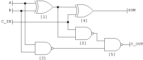
Don't tell anyone, but the VHDL example 'happens' to be an implementation of this circuit. - Now you need to make a 1-bit ALU. It needs to perform the following operations:
Opcode Task Description 0 0000 add Add A and B 1 0001 addu Add, but using unsigned numbers 2 0010 sub Subtract B from A 3 0011 subu Subtract using unsigned numbers 4 0100 and Bitwise AND 5 0101 or Bitwise OR 6 0110 xor Bitwise XOR 7 0111 nor Bitwise NOR a 1010 slt Set (output) 1 if A is less than B b 1011 sltu Slt with unsigned numbers
This is easier than it looks. Here's the declaration for my ALU:
entity alu_1bit is
port (a,b : in std_logic; -- operands to add/subtract/etc
cin : in std_logic; -- carry in, needed to chain multiple ALUs together
less : in std_logic; -- this is the input that determines the result of slt and sltu.
--It's technically only needed in the lowest-order bit (bit 0) of the ALU
op : in std_logic_vector(3 downto 0); -- opcode input, 4 bits
z : out std_logic -- ALU output (the 'answer')
cout : out std_logic -- carry out
addABout : out std_logic -- the output from the full adder.
-- Technically only needed for the highest-order bit (bit 3)
ovf : out std_logic -- Overflow output. Only needed for the highest-order bit
);
end alu_1bit;- The instructions tell you that you'll need special ALUs for the highest and lowest order bits. I've added the 'special' features to my normal 1-bit ALU so that I only need one kind.
- Each of the bitwise operations is trivial. XOR and NOR are in your gate libary, so start by making signals containing A XOR B and A NOR B. NAND is the closest we have to AND, so also make a signal with A NAND B. Remember to use appropriate gate delays.
- For the other operations we'll need to use our full adder. A few notes about these operations:
- There is no difference in the ALU's answer for "signed" or "unsigned" operations. The only difference is in the overflow detection.
- To subtract B from A, we use a trick of two's complement arithmetic: A - B is the same as A + NOT(B) + 1.
- First we'll need to use B for add and the bitwise operations, and NOT(B) for subtract and slt(u). First make a signal called notB containing NOT(B). Then use the when statement to make a multiplexer:
invb <= b when "0000", -- add
b when "0001", -- addu
notB when "0010", -- sub
notB when "0011", -- subu
notB when "1010", --slt
notB when "1011", --sltu
b when others; - Now add your full adder using the port map statement. Input 1 connects to the ALU's input A. Input 2 connects to the invb signal defined above. Carry in connects to carry in. The outputs of the full adder (sum and carry out) should go to signals, since we'll need to use them multiple places. Connect the adder's carry out signal to the ALU's carry out output using a concurrent signal assignment. Also connect the adder's output to the addABout output.
- We're ready to hook up the ALU's output. Using the when statement like we did above, set z as follows: To the full adder sum for add, addu, sub, subu. To NOT(A NAND B) for and, and NOT(A NOR B) for nor. To (A XOR B) for xor and (A NOR B) for nor. (We defined these signals earlier. Remember to use gate delays.) Set z to the "less" input for slt and sltu. This will make sense later. Finally, set z to '0' when others, in case we get a bad opcode.
- The final piece of the ALU is overflow detection. The unsigned operations (addu, subu, sltu) are 'not allowed' to overflow. That just means that we ignore any overflow. The other operations can overflow, so use another when statement. When the opcode is addu, subu, or sltu, set ovf to '0'. For all other cases (when others), set ovf to "cin xor carry". Remember to use gate delay.
- To build a 4-bit ALU, we'll need zero-detect logic. Make an entity with a 4-bit std_logic_vector as an input, and a 1 bit output. To detect a zero, we want to see if all 4 input bits are zero. In logic, this would be IS_ZERO = NOT(INPUT1) AND NOT(INPUT2) AND NOT(INPUT3) AND NOT(INPUT3). Unfortunately, we only have NAND, NOR, NOT, and XOR to work with. Using DeMorgan's theorem, we get that IS_ZERO = NOT( (INPUT1 NOR INPUT2) NAND (INPUT3 NOR INPUT4) ). This is easy to make using 2 NOR gates, 1 NAND gate, and 1 NOT gate, all of which we have.
- Now we're ready to put together a 4-bit ALU. The declaration should look the same as the 1-bit ALU, but inputs A and B and output Z will each be 4 bits using "std_logic_vector(3 downto 0)". It will also have an additional output: 'zero_out'. You'll need to add 4 copies of your 1-bit ALU (4 port map statements). Connect the A and B inputs of each 1-bit ALU to the appropriate bits of the 4-bit inputs. The first ALU gets bit 0 of the inputs, the second gets bits 1, and so on. Connect the opcode inputs to each of the ALUs (each ALU gets all of the opcode). Connect each Z output to a signal so we can use it later. Connect each carry-in to the carry-out of the previous ALU. Connect the 'less' input of the low-order ALU (the one that gets bit 0) to the less input of the 4-bit ALU. Connect '0' to the less input of the other ALUs. Connect the carry in of the low-order ALU to the carry-in of the 4-bit ALU. Connect the carry out of the high-order bit to the 4-bit ALU carry out. Connect the high-order ALU's addABout and ovf outputs to the 4-bit ALU's outputs (leave these unconnected for the other ALUs). Add your zero-detect module. The input is the signal with the Z outputs. The ouput goes to the zero_out output. Finally, connect the Z output signal to the Z output of the 4-bit ALU.
- Now we need 8-bit zero-detect logic for the 32-bit ALU. We want IS_ZERO = ZERO1 and ZERO2 and ZERO3 ... and ZERO 8. This converts to: IS_ZERO = NOT( ( (Z1 NAND Z2) NOR (Z3 NAND Z4) ) NAND ( (Z5 NAND Z6) NOR (Z7 NAND Z8) ) ). Use gate delays, etc.
- We're finally ready to assemble our 32-bit ALU. The declaration is given in the assignment. For every bit unless otherwise noted: Connect the opcode (op to m). Connect the correct part of the 32-bit inputs (A,B) to the 4-bit inputs. Do the same for the output (result). Store zero_out to a signal. Connect carry out to the carry in of the next bit. Connect 'less' to '0'. For the highest-order ALU (31 downto 28): connect ovf to ovf. Connect addABout to a signal. For the lowest-order ALU: (3 downto 0): connect the addABout from the highest ALU to 'less'. Connect carry in to a signal defined as follows: '1' when m is sub, subu, slt, or sltu, '0' when others. This gives us the "+1" we needed to do A-B. Finally connect your 8-bit zero-detect to the signal with the zero_outs, and to the zero output.